SDAPO深圳达普致力于研发,生产,销售POE产品一条龙服务。自有贴片机产线,能更好的把控产品交期和质量。


12V5A IEEE802.3bt 插针式POE模块模组 支持百兆千兆 SDAPO达普
真BT协议POE模块
DESCRIPTION
FEATURES
l Fully supports IEEE802.3af/at/bt
l Small Single In-Line (SIL) package size –62mm (L) x 27mm (H)
l Input Voltage Range 44V to 57V
l Support PoE applications in both of Fast / Gigabit Ethernet environments.
l Short Circuit Protection
l Over-temperature Protection
l Programmable Classification (Default:Class 8)
l High Efficiency
l Isolation level 1.5KVrms.
l Easy Installation and Low Cost (Isolation Type, Minimum External Devices required)
l Adjustable Output Voltage
l 1500Vrms Isolation (Input-Output)
APPLICATION AREAS
l § Security and alarm systems
l § Voice over IP phones
l § Access control systems
l § IP Cameras
l § Displays, Net Monitors
l § Public address systems
l § Wireless access points
l § Environmental control
l § Telemetry
l § Remote environmental monitoring
1 Product Overview
1.1 DP1205BT Product Selector
|
Part Number |
Nominal Output Voltage |
Maximum Output Power * |
|
DP1205 |
12.0V |
60 Watts Peak 50 Watts Continuous |
|
DP1205-24V |
24.0V |
60 Watts Peak 50 Watts Continuous |
*At 25°C with VIN = 52V
Table 1: Ordering Information

Figure 1: Block Diagram
1.2 Pin Description
|
1 |
VA1 |
RX Input (1). This input pin is used in conjunction with VA2 and connects to the centre tap of the transformer connected to pins 1 & 2 of the RJ45 connector (RX) - it is not polarity sensitive. |
|
2 |
VA2 |
TX Input (2). This input pin is used in conjunction with VA1 and connects to the centre tap of the transformer connected to pins 3 & 6 of the RJ45 connector (TX) - it is not polarity sensitive. |
|
3 |
VB1 |
Direct Input (1). This input pin is used in conjunction with VB2 and connects to pin 4 & 5 of the RJ45 connector - it is not polarity sensitive. |
|
4 |
VB2 |
Direct Input (2). This input pin is used in conjunction with VB1 and connects to pin 7 & 8 of the RJ45 connector - it is not polarity sensitive. |
|
5,6 |
NC |
No Connection |
|
|
|
|
|
7,8 |
-VDC |
DC Return. This pin is the return path for the +VDC output. |
|
9.10 |
+VDC |
DC Output. This pin provides the regulated output from the DC/DC converter. |
|
11 |
ADJ |
Output Adjust. The output voltage can be adjusted from is nominal value, by connecting an external resistor from this pin to either the +VDC pin or the - VDC pin |
|
12 |
NC |
No Connection |
2 Functional Description
2.1 Typical Connections

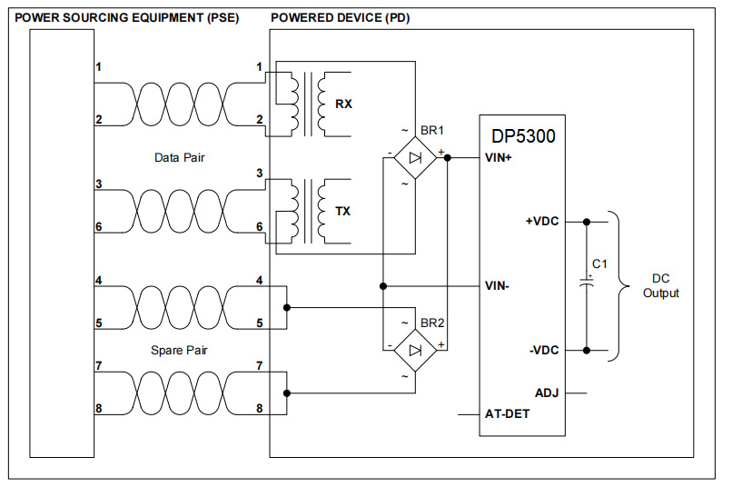
Figure 2: Typical System Diagram
*Note: Suitable bridge rectifier for BR1 & BR2 would be a “MB210S” or equivalent.
2.2 Output Voltage Adjustment
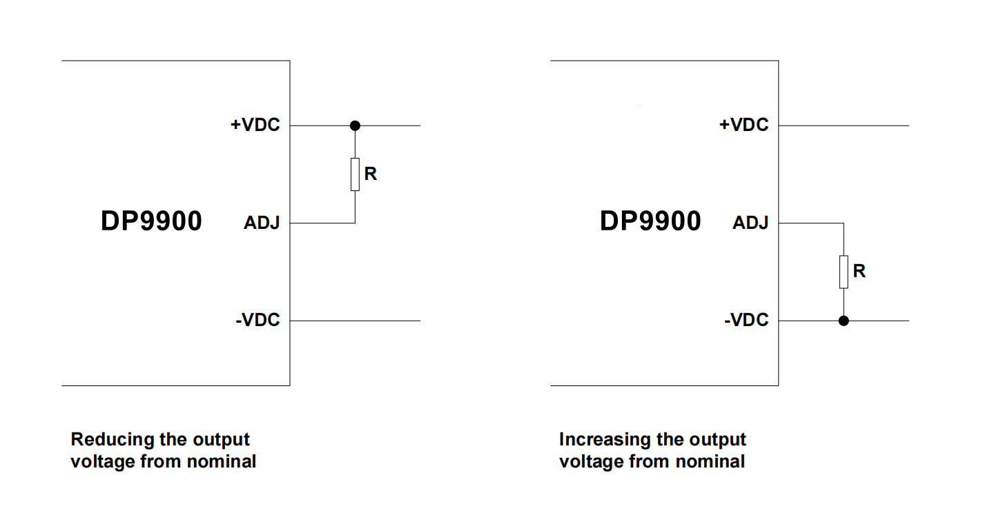
The DP1205 series has an ADJ pin, which allows the output voltage to be increased or decreased.
Figure 3 shows how the ADJ pin is connected.

Figure 3: Output Adjustment
|
Reducing the output voltage, connect R between ADJ and +VDC | ||
|
Value of R |
DP1205 Output |
DP1205-24V Output |
|
Open Circuit |
12.07V |
23.93V |
|
0 Ohms |
10.0V |
19.85V |
|
100K |
11.15V |
21.85V |
|
470k |
11.76V |
23.23V |
|
| ||
|
Increasing the output voltage, connect R between ADJ and -VDC | ||
|
Value of R |
DP1205 Output |
DP1205-24V Output |
|
Open Circuit |
12.07V |
23.93V |
|
0 Ohms |
12.75V |
24.6V |
|
100K |
12.34V |
24.2V |
|
470k |
12.16V |
24.01V |
Table 3: Output Adjustment Resistor (R) Value
3 Electrical Characteristics
3.1Absolute Maximum Ratings
|
|
Parameter |
Symbol |
Min |
Max |
Units |
|
1 |
DC Supply Voltage |
VCC |
-0.3 |
60 |
V |
|
2 |
DC Supply Voltage Surge for 1ms |
VSURGE |
-0.6 |
80 |
V |
|
3 |
Storage Temperature |
TS |
-40 |
+100 |
˚C |
3.2 Recommended Operating Conditions
|
|
Parameter |
Min |
Typ |
Max |
Units |
|
1 |
Input Supply Voltage |
36 |
52 |
57 |
V |
|
2 |
Under Voltage Lockout |
30 |
|
36 |
V |
|
3 |
Operating Temperature |
-40 |
25 |
85 |
℃ |
|
4 |
IEEE 802.3bt |
Class 8 | |||
3.3 DC Electrical Characteristics
|
|
DC Characteristic |
Variant |
Sym |
Min |
Typ1 |
Max |
Units |
|
1 |
Nominal Output Voltage |
DP1205 |
|
11.6 |
12 |
12.4 |
V |
|
2 |
Minimum Load2 |
DP1205 |
|
20 |
|
|
mA |
|
3 |
Output Current (VIN = 52V) |
DP1205 |
|
|
5 |
|
A |
|
4 |
Line Regulation |
DP1205 |
|
|
0.05 |
|
% |
|
5 |
Load Regulation – Min to Max (VIN = 52V) |
DP1205 |
|
|
0.1 |
|
% |
|
6 |
Output Ripple and Noise5@ Max load |
DP1205 |
|
|
80 |
@4A |
mVp-p |
|
7 |
Peak Efficiency |
DP1205 |
|
|
92 |
@4A |
% |
|
8 |
Short-Circuit Duration3 |
|
TSC |
|
|
∞ |
sec |
|
9 |
Isolation Voltage (I/O) - Impulse Test |
|
VISO |
|
|
1500 |
VPK |
Note 1: Typical figures are at 25°C with a nominal 52V supply and are for design aid only. Not Guaranteed
Note 2: The module can emit an audible noise, if operated at less than the stated minimum ILOAD and cause the PSE to fail its MPS.
Note 3: >200mohm short due to thermal limitation.
Note 4:The output ripple and noise can be reduced with an external filter
4 Package


 Establishing PoE Connection – Type 1 (IEEE 802.3af/PoE)

Establishing PoE Connection – Type 2 (IEEE 802.3at/PoE+)

Establishing PoE Connection – Type 3 and 4 (IEEE 802.3bt)

